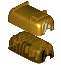
| Core and Cavity Separation (SolidSEP) Easily separate core and cavity geometry from complex surface or Solid models. This excruciating task that once took hours can now be done automatically in a matter of minutes in comparison to hours or days. SolidSEP literally pays for itself the first time you use it! |
 |
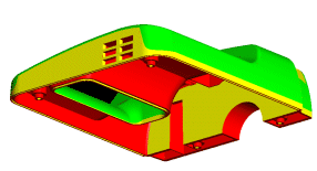
| Draft Angle Analysis Eliminate prototypes and tedious verification with Draft Angle Analysis. Automatically verify if your part can be machined and pulled correctly without generating a toolpath! Easily identify and isolate areas with undercuts. Surfaces are also automatically trimmed for easy knock-out construction. |
 |
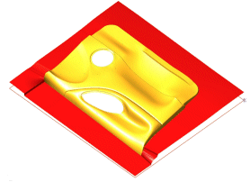
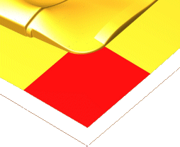
Parting Line creation |
  |
| Automatic Moldlocks Create moldlocks on the corners of mold inserts as side or corner locks. |
|
| Surface Edge Extension tools Easily extend the edges of surfaces\trimmed surfaces tangentially or relative to any defined angle from the surface normal. |
|
| 2D and 3D Edge creation tools Automatically create curve edges only on the outside of the part or on selected surfaces. The part edges can also be projected onto a plane (as 2D edges) for use in contour machining or other reference geometry creation. This powerful function can also be used to verify if all surfaces are coincident. |
|
| Mold Insert Creation \ Stock Electrodes Create square, rectangular, round or free form inserts quickly and automatically. The insert geometry can be isolated, trimmed and rotated ready for machining. |
|
| Cross Sections Create cross sectional curves across or along surface models as single or multiple sections. Complex Surface Trimming Trim single or multiple sets of surfaces with blinding speed. No limitations on trimming pre-trimmed surfaces! Split or delete areas of surface models using boundaries with superior ease! |
|
| Drill Centers and Planar Edges Create planar edges and drill Centers with point and arc information automatically on surface geometry originating from a solids modeler. |
|
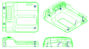
| Automatic Drafting Layout (ISO/ANSI/JIS) Creates drafting ready 2D views from surface or wireframe geometry. ISO/ANSI/JIS standard drafting layouts are provided as defaults. The user can also create custom views. The created geometry can then be used for dimensioning or engraving. |
 |
